Copyright © 2023 NetworkRV LLC. All Rights Reserved.
TURN OFF ALL POWER AND BREAKERS BEFORE STARTING INSTALLATION.
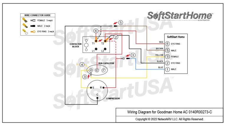
Route all SoftStart wires into the electrical box, then crimp Connectors onto all SoftStart Home wires as indicated in drawing.
Step 1. Follow Red Compressor wire to the T2 terminal on the Contactor Block. Disconnect Red wire from T2, cut off Eye Ring, crimp Female connector on the end, and connect it to Blue SoftStart wire. Tape connection.
Step 2. Connect Black SoftStart wire onto the T2 terminal that the Red wire was on.
Step 3. Connect Yellow SoftStart wire onto an empty HERM (H) terminal next to the Yellow Compressor wire.
Step 4. If there is a second Yellow wire on a HERM terminal next to the Yellow Compressor wire, disconnect it and tape the end.
Step 5. Follow Black Compressor wire FROM Compressor TO the T1 terminal. Disconnect Black Compressor wire and cut off Eye Ring connector. Crimp Female connector on Black Compressor wire, then connect it to Brown SoftStart wire. Tape connection.
Step 6. Connect Red SoftStart wire onto the T1 terminal that the Black Compressor wire was on.
Secure all wires. Tape connections with electrical tape.
Turn Power and A/C Breaker on. Turn A/C to Auto Cool setting and set the thermostat to 55ºF.
Look at SoftStart LED lights. Run LED 1 light should be “on”. Green light means the Compressor is running (there may be a full 3-minute delay before Green light comes on). IF there is no Green light after 4 minutes, call SoftStart Tech Support for assistance.
After establishing Green light operation, re-install all A/C covers.
Turn A/C on, set near to outdoor temperature and run for 30 minutes.
After 30 minutes, operate A/C normally.